Computer structure pipeline презентация
Содержание
- 2. A Basic Processor
- 3. Pipelined Car Assembly
- 5. Pipelining Pipelining does not reduce the latency of single task, it
- 6. Pipelined CPU
- 7. Structural Hazard Different instructions using the same resource at the same
- 8. Pipeline Example: cycle 1
- 9. Pipeline Example: cycle 2
- 10. Pipeline Example: cycle 3
- 11. Pipeline Example: cycle 4
- 12. Pipeline Example: cycle 5
- 13. RAW Dependency
- 14. Using Bypass to Solve RAW Dependency
- 15. RAW Dependency
- 16. Forwarding Hardware
- 17. Forwarding Control Forwarding from EXE (L3) if (L3.RegWrite and (L3.dst ==
- 18. Register File Split Register file is written during first half of
- 19. Can't Always Forward
- 20. Stall If Cannot Forward
- 21. Software Scheduling to Avoid Load Hazards Fast code LW Rb,b LW
- 22. Control Hazards
- 23. Control Hazard on Branches
- 24. Control Hazard on Branches
- 25. Control Hazard on Branches
- 26. Control Hazard on Branches
- 27. Control Hazard on Branches
- 28. Control Hazard on Branches
- 29. Control Hazard: Stall Stall pipe when branch is encountered until resolved
- 30. Control Hazard: Predict Not Taken Execute instructions from the fall-through (not-taken)
- 31. Dynamic Branch Prediction
- 32. BTB Allocation Allocate instructions identified as branches (after decode) Both conditional
- 33. BTB (cont.) Wrong prediction Predict not-taken, actual taken Predict taken, actual
- 34. Adding a BTB to the Pipeline
- 35. Adding a BTB to the Pipeline
- 36. Adding a BTB to the Pipeline
- 37. Using The BTB
- 38. Using The BTB (cont.)
- 39. Backup
- 40. MIPS Instruction Formats
- 41. The Memory Space Each memory location is 8 bit =
- 42. Register File The Register File holds 32 registers Each register is
- 43. Memory Components Inputs Address: address of the memory location we wish
- 44. The Program Counter (PC) Holds the address (in memory) of the
- 45. Instruction Execution Stages Fetch Fetch instruction pointed by PC from I-Cache
- 46. The MIPS CPU
- 47. Executing an Add Instruction
- 48. Executing a Load Instruction
- 49. Executing a Store Instruction
- 50. Executing a BEQ Instruction
- 51. Control Signals
- 52. Pipelined CPU: Load (cycle 1 – Fetch)
- 53. Pipelined CPU: Load (cycle 2 – Dec)
- 54. Pipelined CPU: Load (cycle 3 – Exe)
- 55. Pipelined CPU: Load (cycle 4 – Mem)
- 56. Pipelined CPU: Load (cycle 5 – WB)
- 57. Datapath with Control
- 58. Multi-Cycle Control
- 59. Five Execution Steps Instruction Fetch Use PC to get instruction and
- 60. Five Execution Steps (cont.) Execution ALU is performing one of
- 61. The Store Instruction
- 62. RAW Hazard: SW Solution
- 63. Delayed Branch Define branch to take place AFTER n following instruction
- 64. Delayed Branch Performance Filling 1 delay slot is easy, 2 is
- 65. Скачать презентацию


if (L3.RegWrite and (L3.dst")


")


Both conditional")

Wrong prediction
Predict not-taken, actual taken
Predict taken, actual")


")


Holds the address (in memory) of the")


")
")
")
")
")


Execution
ALU is performing one")


Слайды и текст этой презентации
Слайд 1
Описание слайда:
Computer Structure
Pipeline
Lecturer:
Aharon Kupershtok
Слайд 2
Описание слайда:
A Basic Processor
Слайд 3
Описание слайда:
Pipelined Car Assembly
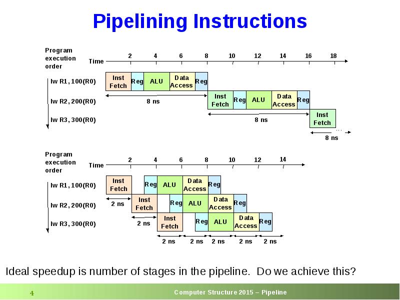
Слайд 4
Описание слайда:
Слайд 5
Описание слайда:
Pipelining
Pipelining does not reduce the latency of single task,
it increases the throughput of entire workload
Potential speedup = Number of pipe stages
Pipeline rate is limited by the slowest pipeline stage
Partition the pipe to many pipe stages
Make the longest pipe stage to be as short as possible
Balance the work in the pipe stages
Pipeline adds overhead (e.g., latches)
Time to “fill” pipeline and time to “drain” it reduces speedup
Stall for dependencies
Too many pipe-stages start to loose performance
IPC of an ideal pipelined machine is 1
Every clock one instruction finishes
Слайд 6
Описание слайда:
Pipelined CPU
Слайд 7
Описание слайда:
Structural Hazard
Different instructions using the same resource at the same time
Register File:
Accessed in 2 stages:
Read during stage 2 (ID)
Write during stage 5 (WB)
Solution: 2 read ports, 1 write port
Memory
Accessed in 2 stages:
Instruction Fetch during stage 1 (IF)
Data read/write during stage 4 (MEM)
Solution: separate instruction cache and data cache
Each functional unit can only be used once per instruction
Each functional unit must be used at the same stage for all instructions
Слайд 8
Описание слайда:
Pipeline Example: cycle 1
Слайд 9
Описание слайда:
Pipeline Example: cycle 2
Слайд 10
Описание слайда:
Pipeline Example: cycle 3
Слайд 11
Описание слайда:
Pipeline Example: cycle 4
Слайд 12
Описание слайда:
Pipeline Example: cycle 5
Слайд 13
Описание слайда:
RAW Dependency
Слайд 14
Описание слайда:
Using Bypass to Solve RAW Dependency
Слайд 15
Описание слайда:
RAW Dependency
Слайд 16
Описание слайда:
Forwarding Hardware
Слайд 17
Описание слайда:
Forwarding Control
Forwarding from EXE (L3)
if (L3.RegWrite and (L3.dst == L2.src1)) ALUSelA = 1
if (L3.RegWrite and (L3.dst == L2.src2)) ALUSelB = 1
Forwarding from MEM (L4)
if (L4.RegWrite and
((not L3.RegWrite) or (L3.dst L2.src1)) and
(L4.dst = L2.src1)) ALUSelA = 2
if (L4.RegWrite and
((not L3.RegWrite) or (L3.dst L2.src2)) and
(L4.dst = L2.src2)) ALUSelB = 2
Слайд 18
Описание слайда:
Register File Split
Register file is written during first half of the cycle
Register file is read during second half of the cycle
Register file is written before it is read returns the correct data
Слайд 19
Описание слайда:
Can't Always Forward
Слайд 20
Описание слайда:
Stall If Cannot Forward
Слайд 21
Описание слайда:
Software Scheduling to Avoid Load Hazards
Fast code
LW Rb,b
LW Rc,c
LW Re,e
ADD Ra,Rb,Rc
LW Rf,f
SW a,Ra
SUB Rd,Re,Rf
SW d,Rd
Слайд 22
Описание слайда:
Control Hazards
Слайд 23
Описание слайда:
Control Hazard on Branches
Слайд 24
Описание слайда:
Control Hazard on Branches
Слайд 25
Описание слайда:
Control Hazard on Branches
Слайд 26
Описание слайда:
Control Hazard on Branches
Слайд 27
Описание слайда:
Control Hazard on Branches
Слайд 28
Описание слайда:
Control Hazard on Branches
Слайд 29
Описание слайда:
Control Hazard: Stall
Stall pipe when branch is encountered until resolved
Stall impact: assumptions
CPI = 1
20% of instructions are branches
Stall 3 cycles on every branch
CPI new = 1 + 0.2 × 3 = 1.6
(CPI new = CPI Ideal + avg. stall cycles / instr.)
We loose 60% of the performance
Слайд 30
Описание слайда:
Control Hazard: Predict Not Taken
Execute instructions from the fall-through (not-taken) path
As if there is no branch
If the branch is not-taken (~50%), no penalty is paid
If branch actually taken
Flush the fall-through path instructions before they change the machine state (memory / registers)
Fetch the instructions from the correct (taken) path
Assuming ~50% branches not taken on average
CPI new = 1 + (0.2 × 0.5) × 3 = 1.3
Слайд 31
Описание слайда:
Dynamic Branch Prediction
Слайд 32
Описание слайда:
BTB
Allocation
Allocate instructions identified as branches (after decode)
Both conditional and unconditional branches are allocated
Not taken branches need not be allocated
BTB miss implicitly predicts not-taken
Prediction
BTB lookup is done parallel to IC lookup
BTB provides
Indication that the instruction is a branch (BTB hits)
Branch predicted target
Branch predicted direction
Branch predicted type (e.g., conditional, unconditional)
Update (when branch outcome is known)
Branch target
Branch history (taken / not-taken)
Слайд 33
Описание слайда:
BTB (cont.)
Wrong prediction
Predict not-taken, actual taken
Predict taken, actual not-taken, or actual taken but wrong target
In case of wrong prediction – flush the pipeline
Reset latches (same as making all instructions to be NOPs)
Select the PC source to be from the correct path
Need get the fall-through with the branch
Start fetching instruction from correct path
Assuming P% correct prediction rate
CPI new = 1 + (0.2 × (1-P)) × 3
For example, if P=0.7
CPI new = 1 + (0.2 × 0.3) × 3 = 1.18
Слайд 34
Описание слайда:
Adding a BTB to the Pipeline
Слайд 35
Описание слайда:
Adding a BTB to the Pipeline
Слайд 36
Описание слайда:
Adding a BTB to the Pipeline
Слайд 37
Описание слайда:
Using The BTB
Слайд 38
Описание слайда:
Using The BTB (cont.)
Слайд 39
Описание слайда:
Backup
Слайд 40
Описание слайда:
MIPS Instruction Formats
Слайд 41
Описание слайда:
The Memory Space
Each memory location
is 8 bit = 1 byte wide
has an address
We assume 32 byte address
An address space of 232 bytes
Memory stores both instructions and data
Each instruction is 32 bit wide stored in 4 consecutive bytes in memory
Various data types have different width
Слайд 42
Описание слайда:
Register File
The Register File holds 32 registers
Each register is 32 bit wide
The RF supports parallel
reading any two registers and
writing any register
Inputs
Read reg 1/2: #register whose value will be output on Read data 1/2
RegWrite: write enable
Слайд 43
Описание слайда:
Memory Components
Inputs
Address: address of the memory location we wish to access
Read: read data from location
Write: write data into location
Write data (relevant when Write=1) data to be written into specified location
Outputs
Read data (relevant when Read=1) data read from specified location
Слайд 44
Описание слайда:
The Program Counter (PC)
Holds the address (in memory) of the next instruction to be executed
After each instruction, advanced to point to the next instruction
If the current instruction is not a taken branch,
the next instruction resides right after the current instruction
PC PC + 4
If the current instruction is a taken branch,
the next instruction resides at the branch target
PC target (absolute jump)
PC PC + 4 + offset×4 (relative jump)
Слайд 45
Описание слайда:
Instruction Execution Stages
Fetch
Fetch instruction pointed by PC from I-Cache
Decode
Decode instruction (generate control signals)
Fetch operands from register file
Execute
For a memory access: calculate effective address
For an ALU operation: execute operation in ALU
For a branch: calculate condition and target
Memory Access
For load: read data from memory
For store: write data into memory
Write Back
Write result back to register file
update program counter
Слайд 46
Описание слайда:
The MIPS CPU
Слайд 47
Описание слайда:
Executing an Add Instruction
Слайд 48
Описание слайда:
Executing a Load Instruction
Слайд 49
Описание слайда:
Executing a Store Instruction
Слайд 50
Описание слайда:
Executing a BEQ Instruction
Слайд 51
Описание слайда:
Control Signals
Слайд 52
Описание слайда:
Pipelined CPU: Load (cycle 1 – Fetch)
Слайд 53
Описание слайда:
Pipelined CPU: Load (cycle 2 – Dec)
Слайд 54
Описание слайда:
Pipelined CPU: Load (cycle 3 – Exe)
Слайд 55
Описание слайда:
Pipelined CPU: Load (cycle 4 – Mem)
Слайд 56
Описание слайда:
Pipelined CPU: Load (cycle 5 – WB)
Слайд 57
Описание слайда:
Datapath with Control
Слайд 58
Описание слайда:
Multi-Cycle Control
Слайд 59
Описание слайда:
Five Execution Steps
Instruction Fetch
Use PC to get instruction and put it in the Instruction Register.
Increment the PC by 4 and put the result back in the PC.
IR = Memory[PC];
PC = PC + 4;
Instruction Decode and Register Fetch
Read registers rs and rt
Compute the branch address
A = Reg[IR[25-21]];
B = Reg[IR[20-16]];
ALUOut = PC + (sign-extend(IR[15-0]) << 2);
We aren't setting any control lines based on the instruction type
(we are busy "decoding" it in our control logic)
Слайд 60
Описание слайда:
Five Execution Steps (cont.)
Execution
ALU is performing one of three functions, based on instruction type:
Memory Reference: effective address calculation.
ALUOut = A + sign-extend(IR[15-0]);
R-type:
ALUOut = A op B;
Branch:
if (A==B) PC = ALUOut;
Memory Access or R-type instruction completion
Write-back step
Слайд 61
Описание слайда:
The Store Instruction
Слайд 62
Описание слайда:
RAW Hazard: SW Solution
Слайд 63
Описание слайда:
Delayed Branch
Define branch to take place AFTER n following instruction
HW executes n instructions following the branch regardless of branch is taken or not
SW puts in the n slots following the branch instructions that need to be executed regardless of branch resolution
Instructions that are before the branch instruction, or
Instructions from the converged path after the branch
If cannot find independent instructions, put NOP
Слайд 64
Описание слайда:
Delayed Branch Performance
Filling 1 delay slot is easy, 2 is hard, 3 is harder
Assuming we can effectively fill d% of the delayed slots
CPInew = 1 + 0.2 × (3 × (1-d))
For example, for d=0.5, we get CPInew = 1.3
Mixing architecture with micro-arch
New generations requires more delay slots
Cause computability issues between generations
Скачать презентацию на тему Computer structure pipeline можно ниже: