Internal Сombustion Engine. Fuel Systems. The diesel injection system презентация
Содержание
- 2. Basic Functions of Injection Systems The basic functions of a diesel
- 3. Basic Functions of Injection Systems 3. Fuel metering that precisely meters
- 4. Types of Injection Systems The basic functions described above are
- 6. Types of Injection Systems Accumulator systems on the other hand have
- 8. Types The implementation of common rail systems in virtually every engine
- 9. Inline Pumps Main Features – There is one pump element per
- 10. Axial Distributor Pumps Main Features – There is one axial pump
- 11. Radial Distributor Pumps – The fuel flow is distributed to outlets
- 12. Unit Injectors (Unit Injectors) Main Features – One unit injector per
- 13. Unit Pump Systems (Unit Pumps) – It is driven by an
- 14. Common Rail System – One injector (body with nozzle and control
- 15. Common Rail System Design Unlike cam-driven injection systems, the common rail
- 16. A common rail system can be divided into the following subsystems
- 17. Common Rail System Design Driven by the engine, the continuously operating
- 18. CR Injectors Common rail injectors with identical basic functions are employed
- 19. Solenoid Valve Injector. Design Configuration An injector can be broken down
- 20. Solenoid Valve Injector. Function The injector’s function can be subdivided into
- 22. Injector opened: The nozzle needle’s opening speed is determined by the
- 23. Injector closes (end of injection): When the solenoid valve is deenergized,
- 24. Скачать презентацию


Main Features
– One unit injector per")

– It is driven by an")


: When the solenoid valve is deenergized,")
Слайды и текст этой презентации
Слайд 1
Описание слайда:
Internal Сombustion Engine
Слайд 2
Описание слайда:
Basic Functions of Injection Systems
The basic functions of a diesel injection system can be broken down into four subfunctions:
1. Fuel delivery (low pressure side) from the tank through the fuel filter to high pressure generation. This function is assumed by the ‘‘low pressure circuit’’ subsystem, which is generally equipped with the components of pre-filter, main filter (heated if necessary), feed pump and control valves.
The low pressure circuit connects the vehicle tank to the high pressure system feed and return by lines through the low pressure components. The functionally determinative pressure and flow specifications of the connected high and low pressure components must be observed.
2. High pressure generation and fuel delivery (high pressure side) to the metering point or in an accumulator with high efficiency during compression. Optimal steady state and dynamic injection pressure both have to be provided as a function of the engine operating point. The required injected fuel quantity and system-dependent control and leak quantities have to be delivered. This function is assumed by the high pressure pump and, depending on the system, an accumulator. Valves are installed in the high pressure circuit to control the mass flows and pressures. In advanced injection systems, they are electronically actuated.
Слайд 3
Описание слайда:
Basic Functions of Injection Systems
3. Fuel metering that precisely meters the fuel mass into the combustion chamber as a function of speed and engine load and is supported by exhaust gas aftertreatment systems. Advanced injection systems meter fuel with the aid of electrically actuated solenoid or piezo valves mounted on the high pressure pumps or directly on the injectors.
4. Fuel preparation by optimally utilizing the pressure energy for primary mixture formation for the purpose of a fluid spray that is optimally distributed in the combustion chamber in terms of time and location. The fuel is prepared in the injection nozzle. The metering valve’s interaction with the nozzle needle control and the routing of the flow from the nozzle inlet until its discharge at the nozzle holes are of key importance.
Слайд 4
Описание слайда:
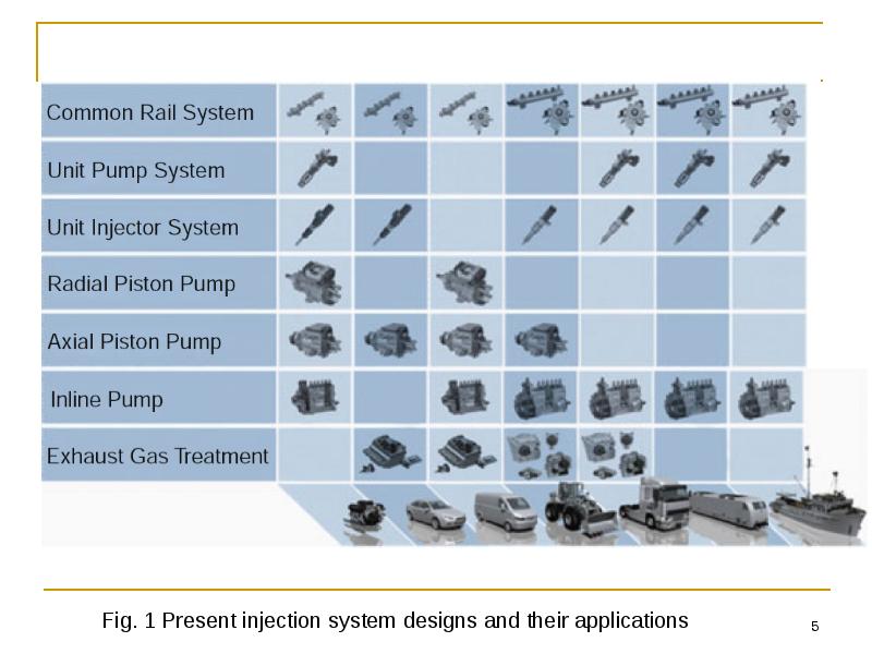
Types of Injection Systems
The basic functions described above are implemented differently depending on the type of injection system.
Figure 1 presents an overview of commercially available injection systems and typical fields of application.
An initial distinction must be made between conventionally designed systems and systems with high pressure accumulators. Injection systems without accumulators always have high pressure pump plungers driven directly by a cam and thus generate a pressure wave in the high pressure system, which is directly utilized to open the injection nozzle and inject the fuel cylinder-selectively according to the firing sequence.
The next level of classification includes systems with a ‘‘central injection pump’’ that serves every cylinder and delivers and meters the fuel. Typical representatives are inline pumps and distributor pumps with axial and radial pump elements.
The other design is characterized by ‘‘detached injection pumps per engine cylinder’’. One discrete pressure generation unit driven by the engine camshaft is attached for every one of the combustion engine’s cylinders. The fuel is metered by rapidly switching solenoid valves integrated in the pump unit. The unit injector is one familiar example of this type of injection system.
Слайд 5
Описание слайда:
Слайд 6
Описание слайда:
Types of Injection Systems
Accumulator systems on the other hand have a central high pressure pump that compresses the fuel and delivers it to an accumulator at high pressure. Low pressure and high pressure valves control the pressure in the accumulator. The fuel is metered from the accumulator by injectors, which are in turn controlled by solenoid or piezoelectric valves.
The name common rail system stems from the ‘‘common accumulator/ distributor’’. Based on the type of actuator in the injectors, a distinction is made between ‘‘solenoid common rail’’ systems and ‘‘piezoelectric common rail’’ systems as well as special designs.
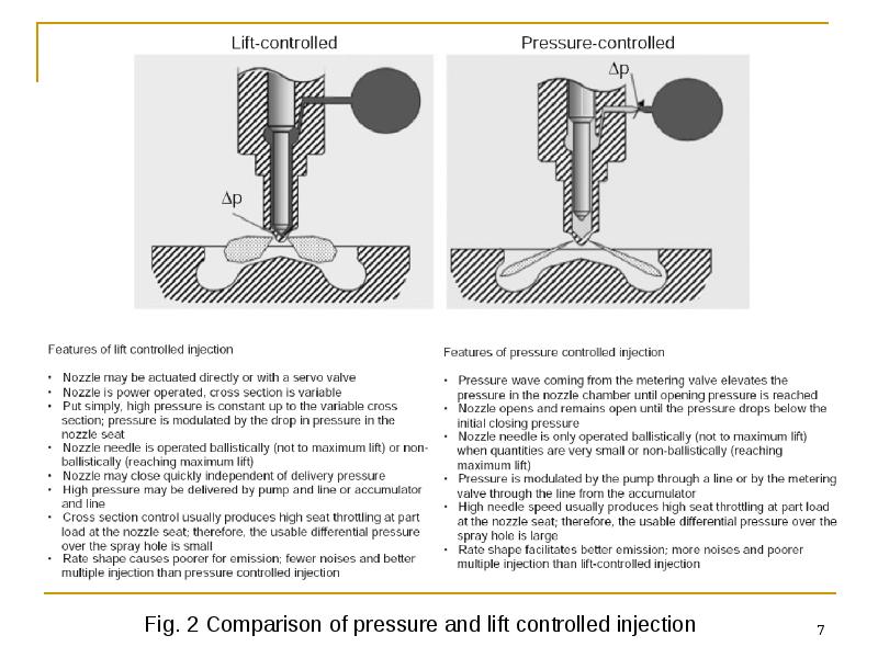
Nozzle needle lift/pressure control:
All injection systems prepare the fuel independently of the design of the injection nozzle, which is either connected with the pump unit by a high pressure line or directly integrated in the pump unit housing or in the injector. The type of nozzle needle control is a main feature that sets conventional and common rail injection systems apart. While the nozzle needle in cam-driven injection systems is ‘‘pressure controlled’’, the injector in common rail systems is ‘‘lift controlled’’.
Figure 2 compares the types of nozzle needle control and summarizes their main features.
Слайд 7
Описание слайда:
Слайд 8
Описание слайда:
Types
The implementation of common rail systems in virtually every engine can be expected in the future. Since they are more flexible than conventional designs, these injection systems are already the main application for cars.
The capability to freely select the pressure and the number of injections per working cycle as a function of engine speed and load and other parameters is indispensible to fulfilling the target engine parameters. Moreover, an accumulator makes it possible to situate injection very late relative to the engine crank angle to control exhaust gas aftertreatment. This will be essential for compliance with future emission standards.
Although a pressure controlled nozzle needle also has advantages for emissions, it is foregone in favor of flexible multiple injections and the lift control of the nozzle needle in common rail injectors is relied on. In an analysis of the overall system, the advantages of lift controlled fuel metering in terms of precision, minimum injected fuel quantity and minimum spray intervals outweigh those of conventional systems with pressure controlled needles.
Слайд 9
Описание слайда:
Inline Pumps
Main Features
– There is one pump element per engine cylinder and the elements are arranged inline.
– The plunger is driven by the pump camshaft and reset by the plunger spring and the plunger stroke is constant.
– Delivery starts when the plunger closes the spill ports.
– The plunger compresses fuel when it moves upward and delivers it to the nozzle.
– The nozzle operates pressure controlled.
Слайд 10
Описание слайда:
Axial Distributor Pumps
Main Features
– There is one axial pump elements for all engine cylinders.
– The cam plate is driven by the engine camshaft and the number of cams equals the number of engine cylinders.
– Cam lobes roll on the roller ring and this generates rotary and longitudinal motion of the distributor plunger.
– A central distributor plunger opens and closes ports and bores.
Слайд 11
Описание слайда:
Radial Distributor Pumps
– The fuel flow is distributed to outlets to the engine cylinders.
– A solenoid valve controls the injected fuel quantity (and start of delivery).
– High pressure builds when the solenoid valve is closed.
– The start of delivery is varied by a solenoid controlled injection timing mechanism, which rotates the cam ring relative to the distributor shaft.
Слайд 12
Описание слайда:
Unit Injectors (Unit Injectors)
Main Features
– One unit injector per engine cylinder is integrated in the engine’s cylinder head.
– It is driven by the engine camshaft by means of an injection cam and tappet or roller rocker.
– High pressure is generated by a pump plunger with spring return.
– High pressure is locally generated directly before the nozzle. Hence, there is no high pressure line.
– The nozzle operates pressure controlled.
– A solenoid valve controls the injected fuel quantity and start of injection.
– High pressure builds when the solenoid valve is closed.
– A control unit computes and controls injection.
Слайд 13
Описание слайда:
Unit Pump Systems (Unit Pumps)
– It is driven by an underhead engine camshaft (commercial vehicles).
– The nozzle operates pressure controlled.
– A high pressure solenoid valve controls the injected fuel quantity and start of injection.
Слайд 14
Описание слайда:
Common Rail System
– One injector (body with nozzle and control valve [solenoid or piezo actuator]) is mounted per engine cylinder.
– The nozzle operates lift controlled.
– The injector operates time controlled and the injected fuel quantity is a function of the rail pressure and duration of control.
– A control unit controls the number and position of injections and the injected fuel quantity.
Слайд 15
Описание слайда:
Common Rail System Design
Unlike cam-driven injection systems, the common rail system decouples pressure generation and injection. The pressure is generated independently from the injection cycle by a high pressure pump that delivers the fuel under injection pressure to an accumulator volume or rail. Short high pressure lines connect the rail with the engine cylinders’ injectors. The injectors are actuated by electrically controlled valves and inject the fuel into the engine’s combustion chamber at the desired time. The injection timing and injected fuel quantity are not coupled with the high pressure pump’s delivery phase. Separating the functions of pressure generation and fuel injection renders the injection pressure independent of speed and load. This produces the following advantages over cam driven systems:
– continually available speed and load-independent injection pressure allows flexibly selecting the start of injection, the injected fuel quantity and the duration of injection,
– high injection pressures and thus good mixture formation are possible even at lower speeds and loads,
– it provides high flexibility for multiple injections,
– it is easily mounted on the engine and
– drive torque peaks are significantly lower.
Common rail systems are employed in all DI engine applications for cars and commercial vehicles (on and off-highway).
Maximum system pressures are 1,800 bar. Systems for pressures > 2,000 bar are in development.
Слайд 16
Описание слайда:
A common rail system can be divided into the following subsystems (Fig. 9):
A common rail system can be divided into the following subsystems (Fig. 9):
– low pressure system with the fuel supply components (fuel tank, fuel filter, presupply pump and fuel lines),
– high pressure system with the components of high pressure pump, rail, injectors, rail pressure sensor, pressure control valve or pressure limiting valve and high pressure lines and
– electronic diesel control with control unit, sensors and actuators.
Слайд 17
Описание слайда:
Common Rail System Design
Driven by the engine, the continuously operating high pressure pump generates the desired system pressure and maintains it largely independent of engine speed and the injected fuel quantity. Given its nearly uniform delivery, the pump is smaller in size and generates a smaller peak driving torque than pumps in other injection systems.
The high pressure pump is designed as a radial piston pump and, for commercial vehicles, partly as an inline or single plunger pump (driven by the engine camshaft). Various modes are employed to control rail pressure. The pressure may be controlled on the high pressure side by a pressure control valve or on the low pressure side by a metering unit integrated in the pump (housed in a separate component for single plunger pumps). Dual actuator systems combine the advantages of both systems. Short high pressure lines connect the injectors with the rail. The engine control unit controls the solenoid valve integrated in the injector to open and reclose the injection nozzle. The opening time and system pressure determine the injected fuel quantity. At constant pressure, it is proportional to the time the solenoid valve is switched on and thus independent of engine and pump speed.
A basic distinction is made between systems with and without pressure amplification. In systems with pressure amplification, a stepped piston in the injector amplifies the pressure generated by the high pressure pump. The injection characteristic can be shaped flexibly when the pressure intensifier is separately controllable by its own solenoid valve. The systems predominantly in use today operate without pressure amplification.
Слайд 18
Описание слайда:
CR Injectors
Common rail injectors with identical basic functions are employed in car and commercial vehicle systems. An injector primarily consists of an injection nozzle, injector body, control valve and control chamber. The control valve has a solenoid or piezo actuator. Both actuators allow multiple injections. The advantage of the piezo actuator’s large actuating force and short switching time can only be exploited when injector design has been optimized to do so.
Injectors in a common rail diesel injection system are connected with the rail by short high pressure fuel lines. A copper gasket seals the injectors from the combustion chamber. Clamping elements attach the injectors in the cylinder head. Common rail injectors are suited for straight or oblique installation in direct injection diesel engines, depending on the design of the injection nozzles.
The system characteristically generates injection pressure independent of the engine speed and the injected fuel quantity. The electrically controllable injector controls the start of injection and the injected fuel quantity. The electronic diesel control’s (EDC) angle-time function controls the injection timing. It requires two sensors on the crankshaft and on the camshaft for cylinder recognition (phase detection).
Various types of injectors are currently standard:
– solenoid valve (SV) injectors with a one or two-piece armature (Bosch),
– inline SV injectors (Delphi),
– tophead piezo injectors (Siemens) and inline piezo injectors (Bosch, Denso).
Слайд 19
Описание слайда:
Solenoid Valve Injector. Design
Configuration
An injector can be broken down into different functional groups:
– the hole-type nozzle,
– the hydraulic servo system and
– the solenoid valve.
The fuel is conducted from the high pressure port (Fig. 10, Pos. 13) through an inlet passage to the injection nozzle and through the inlet throttle (14) into the valve control chamber (6). The valve control chamber is connected with the fuel return (1) by an outlet throttle (12) that can be opened by a solenoid valve.
Слайд 20
Описание слайда:
Solenoid Valve Injector. Function
The injector’s function can be subdivided into four operating states when the engine is running and the high pressure pump is delivering fuel:
– injector closed (with adjacent high pressure),
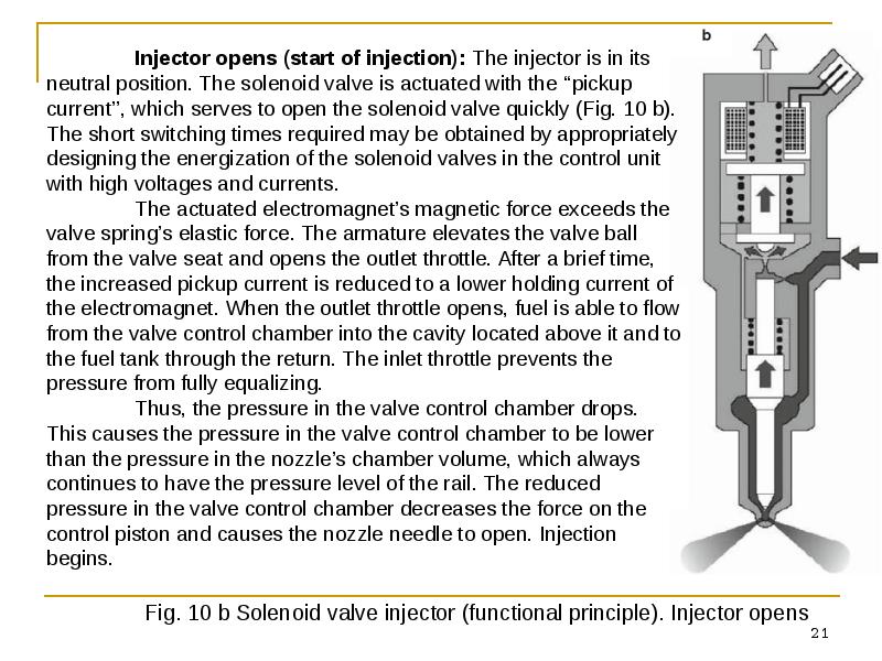
– injector opens (start of injection),
– injector opened and
– injector closes (end of injection).
These operating states are regulated by the distribution of forces to the injector’s components. The nozzle spring (7) closes the injector when the engine is not running and there is no pressure in the rail.
Injector closed (resting state): The injector is not actuated in its resting state (Fig. 10 a). The solenoid valve spring (11) presses the valve ball (5) into the seat of the outlet throttle (12). The rail’s high pressure is generated in the valve control chamber. The same pressure also exists in the nozzle’s chamber volume (9). The forces applied to the lateral face of the valve piston (15) by the rail pressure and the force from the nozzle spring (7) hold the nozzle needle closed against the opening force acting on its pressure shoulder (8).
Слайд 21
Описание слайда:
Слайд 22
Описание слайда:
Injector opened: The nozzle needle’s opening speed is determined by the differential flow between the inlet and outlet throttles. The control piston reaches its top position and remains there on a fuel cushion (hydraulic stop). The cushion is generated by the fuel flow produced between the inlet and outlet throttles. The injector nozzle is then fully opened. The fuel is injected into the combustion chamber at a pressure approximating the pressure in the rail.
Injector opened: The nozzle needle’s opening speed is determined by the differential flow between the inlet and outlet throttles. The control piston reaches its top position and remains there on a fuel cushion (hydraulic stop). The cushion is generated by the fuel flow produced between the inlet and outlet throttles. The injector nozzle is then fully opened. The fuel is injected into the combustion chamber at a pressure approximating the pressure in the rail.
At the given pressure, the injected fuel quantity is proportional to the solenoid valve’s operating time and independent of the engine and pump speed (time controlled injection).
Слайд 23
Описание слайда:
Injector closes (end of injection): When the solenoid valve is deenergized, the valve spring pushes the armature downward, whereupon the valve ball closes the outlet throttle (Fig. 10 c). The closing of the outlet throttle causes the inlet throttle to build up rail pressure in the control chamber again. This pressure exerts increased force on the control piston. The force from the valve control chamber and the force from the nozzle spring then exceed the force acting on the nozzle needle from below and the nozzle needle closes.
Injector closes (end of injection): When the solenoid valve is deenergized, the valve spring pushes the armature downward, whereupon the valve ball closes the outlet throttle (Fig. 10 c). The closing of the outlet throttle causes the inlet throttle to build up rail pressure in the control chamber again. This pressure exerts increased force on the control piston. The force from the valve control chamber and the force from the nozzle spring then exceed the force acting on the nozzle needle from below and the nozzle needle closes.
The flow from the inlet throttle determines the nozzle needle’s closing speed. Injection ends when the nozzle needle reaches the nozzle body seat again and thus closes the spray holes.
This indirect control of the nozzle needle by a hydraulic force boost system is employed because the forces needed to quickly open the nozzle needle cannot be generated directly with the solenoid valve. The ‘‘control quantity’’ required in addition to the injected fuel quantity reaches the fuel return through the control chamber’s throttles. In addition to the control quantity, leakage quantities are in the nozzle needle and the valve piston guide. The control and leakage quantities are returned to the fuel tank by the return with a manifold to which the overflow valve, high pressure pump and pressure control valve are also connected.
Скачать презентацию на тему Internal Сombustion Engine. Fuel Systems. The diesel injection system можно ниже: