Lin protocol description. Automotive body network презентация
Содержание
- 2. Automotive Body Network
- 3. Typical LIN Applications
- 4. MUX Standards (Costs and Speeds)
- 5. LIN Consortium Consortium formed in 1998. Five Car manufacturers ONE Semiconductor
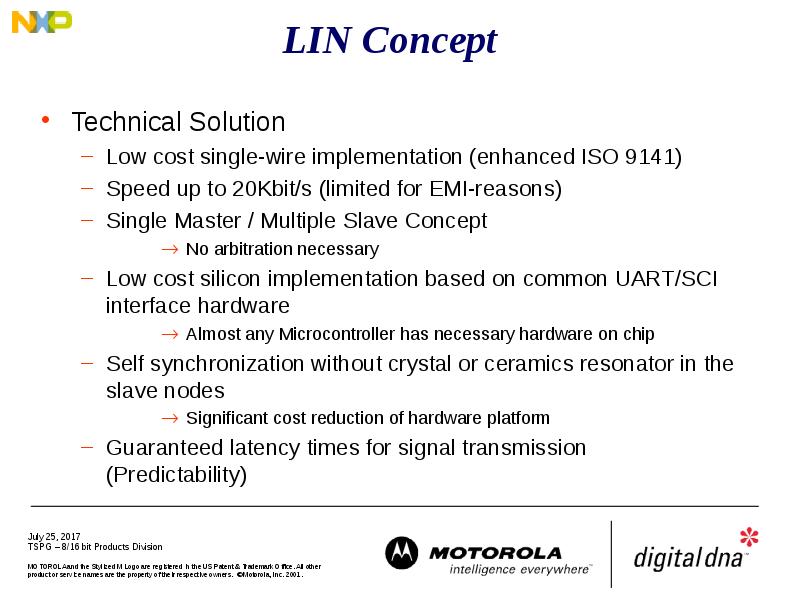
- 6. LIN Standard - Overview
- 7. Hierarchical Network Structure
- 8. Sub-Network: LIN vs. CAN
- 9. SubNets Necessary to reduce Busload on main Bus Solutions CAN Automotive
- 10. Sub Bus Concept Basic Requirements: Satisfy Need for a Standard for
- 12. Master / Slave Protocol Master Task Determines order and priority of
- 13. Master / Slave Protocol Master has control over the whole Bus
- 14. Master/Slave Protocol Slave Is one of 2-16 Members on the Bus
- 15. LIN protocol offers message timing predictability Time Triggered Approach
- 16. Data Transmission
- 17. Message Frame Synch Byte: Specific Pattern for Determination of Time Base
- 18. Identifier The identifier field is sent by the master node to
- 19. LIN Message Frame
- 20. LIN Communication - Data from Slave to Master
- 21. LIN Communication - Data from Master to Slave(s)
- 22. LIN Communication - Data from Slave to Slave
- 23. LIN Message Frame
- 24. Frame Synchronisation (1)
- 25. Frame Synchronisation (2)
- 26. Bit-Synchronisation A start bit transition to a low logic level (dominant)
- 27. Bit Sampling
- 28. Bit-Synchronisation
- 29. Taking account of Ground-Shift
- 30. LIN Physical Interface
- 31. Examination of whether the Deadline is met
- 32. Message latency
- 33. Message latency across a network
- 34. Latency optimisation with LIN
- 35. Variables Scheduling
- 36. Event Triggered Message Problem Specific node communication required but this takes
- 37. Further information http://www.lin-subbus.org
- 38. LIN Development Flow
- 39. LIN Configuration Description File Includes all essential information of network signals,
- 40. The Workflow Data Input Definition of objects Definition of relations between
- 41. Скачать презентацию


")


")


")
")
")


Слайды и текст этой презентации
Слайд 1
Описание слайда:
LIN protocol description
Слайд 2
Описание слайда:
Automotive Body Network
Слайд 3
Описание слайда:
Typical LIN Applications
Слайд 4
Описание слайда:
MUX Standards (Costs and Speeds)
Слайд 5
Описание слайда:
LIN Consortium
Consortium formed in 1998.
Five Car manufacturers
ONE Semiconductor Supplier (Motorola)
One tool Supplier (VCT)
Specification finalised on 02/02/00
Official Launch at SAE March ‘00
Open Specification.
Motorola Ready to support LIN with extensive
device families and new parts already in the
discussion/ spec finalization loop.
First dedicated LIN part available Q3 ‘00
Слайд 6
Описание слайда:
LIN Standard - Overview
Слайд 7
Описание слайда:
Hierarchical Network Structure
Слайд 8
Описание слайда:
Sub-Network: LIN vs. CAN
Слайд 9
Описание слайда:
SubNets
Necessary to reduce Busload on main Bus
Solutions
CAN
Automotive Standard Bus
Compatible with Main Bus
Expensive (Die Size/ Dual Wire)
Serial Sub Bus
no standard Bus System
not compatible with Main Bus
inexpensive
SCI-Based: Interface exists even on cheap devices
Interface can easily be reconstructed by ASIC or CPLD
Слайд 10
Описание слайда:
Sub Bus Concept
Basic Requirements:
Satisfy Need for a Standard for Sub Busses
Cost driven: The solution must be cheaper than CAN
Reliability: Same Level as CAN expected
Long Term Solution
Logical Extension to CAN
Scalable: Capability to extend Systems with additional nodes
Lowering Cost of Satellite nodes:
No Crystal or Resonator
Easy implementation
Simple State Machines
Low Reaction Time (100 ms max)
Predictable Worst Case Timing
Слайд 11
Описание слайда:
Слайд 12
Описание слайда:
Master / Slave Protocol
Master Task
Determines order and priority of messages.
Monitors Data and check byte and controls the error handler.
Serves as a reference with its clock base (stable clock necessary)
Receives Wake- Up Break from slave nodes
Slave Task
Is one of 2-16 members on the bus
Receives or transmits data when an appropriate ID is sent by the master.
The node serving as a master can be slave, too!
Слайд 13
Описание слайда:
Master / Slave Protocol
Master
has control over the whole Bus and Protocol
The master controls which message at what time is to be transferred over the bus. It also does the error handling.
To accomplish this the master
sends Sync Break
sends Sync Byte
sends ID-Field
monitors Data Bytes and Check Byte, and evaluates them on consistance
receives WakeUp Break from slave nodes when the bus is inactive and they request some action.
serves as a reference with it’s clock base (stable clock necessary)
Слайд 14
Описание слайда:
Master/Slave Protocol
Slave
Is one of 2-16 Members on the Bus and receives or transmits Data when an appropriate ID is sent by the master.
Slave snoops for ID.
According to ID, slave determines what to do.
either receive data
or transmit data
or do nothing.
When transmitting the slave
sends 1, 2, 4, or 8 Data Bytes
sends Check-Byte
The node serving as a master can be slave, too!
Слайд 15
Описание слайда:
LIN protocol offers message timing predictability
Time Triggered Approach
Message Length is known
Number of transmitted data bytes is known
minimum length can be calculated
Each Message has length budget of 140% of it’s minimum length
maximum allowed length is known
distance between beginning of two messages
Слайд 16
Описание слайда:
Data Transmission
Слайд 17
Описание слайда:
Message Frame
Synch Byte:
Specific Pattern for Determination of Time Base
(Determination of the time between two rising edges)
A Synch Byte precedes any Message Frame
ID-Field:
Message Identifier: Incorporates Information about the sender, the receiver(s), the purpose, and the Data field length.
Length 6 Bit.
4 classes of 1/2/4/8 Data Bytes. The length coding is in the
2 LSB of the ID-Field. Each class has 16 Identifiers. A total of 64 Message Identifiers are possible.
2 Parity Bits protect this highly sensitive ID-Field.
Слайд 18
Описание слайда:
Identifier
The identifier field is sent by the master node to all LIN nodes
This identifier normally contains one of 64 different values and includes 2 parity bits in the 8 bit data
The identifier is normally associated with a collection of signals that are subsequently transmitted on the LIN bus
In a specific case this can initiate SLEEP mode in the LIN slave nodes – in this case no further data is transmitted on the LIN bus
Слайд 19
Описание слайда:
LIN Message Frame
Слайд 20
Описание слайда:
LIN Communication - Data from Slave to Master
Слайд 21
Описание слайда:
LIN Communication - Data from Master to Slave(s)
Слайд 22
Описание слайда:
LIN Communication - Data from Slave to Slave
Слайд 23
Описание слайда:
LIN Message Frame
Слайд 24
Описание слайда:
Frame Synchronisation (1)
Слайд 25
Описание слайда:
Frame Synchronisation (2)
Слайд 26
Описание слайда:
Bit-Synchronisation
A start bit transition to a low logic level (dominant) indicates a start of a byte, least significiant first and completing with a logic high level (resessive) bit to indicate the STOP bit
Слайд 27
Описание слайда:
Bit Sampling
Слайд 28
Описание слайда:
Bit-Synchronisation
Слайд 29
Описание слайда:
Taking account of Ground-Shift
Слайд 30
Описание слайда:
LIN Physical Interface
Слайд 31
Описание слайда:
Examination of whether the Deadline is met
Слайд 32
Описание слайда:
Message latency
Слайд 33
Описание слайда:
Message latency across a network
Слайд 34
Описание слайда:
Latency optimisation with LIN
Слайд 35
Описание слайда:
Variables Scheduling
Слайд 36
Описание слайда:
Event Triggered Message
Problem
Specific node communication required but this takes up too much time for all network messages
Solution : Event Triggered frame:
Header is sent out
normal case: no answer
Rare response: only one node responds
Very rare response : several nodes respond simultaneously
Cases 1 and 3 are exceptions that should be addressed at the application design.
Event triggered messaging is complementary to the regular signal based messaging scheme
Слайд 37
Описание слайда:
Further information
http://www.lin-subbus.org
Слайд 38
Описание слайда:
LIN Development Flow
Слайд 39
Описание слайда:
LIN Configuration Description File
Includes all essential information of network signals, latency periods, cycle times, nodes affected
Input file serves as a development interface for a node
LIN Application Generator
LIN-Emulator
LIN Analyser
Слайд 40
Описание слайда:
The Workflow
Data Input
Definition of objects
Definition of relations between the objects
Data Processing
Signal Packing (Frame Editor/Frame Compiler)
Timing Analysis
Data Output
Configuration file generation
Various optional customer-defined post-operations
Скачать презентацию на тему Lin protocol description. Automotive body network можно ниже: