Piping Task презентация
Содержание
- 2. Agenda Piping Hierarchy Route Pipes Inserting Components Routing a Sloped Pipe
- 3. Agenda Conti’ Manipulating Views Creating Spools Sequencing Objects Creating Isometric Drawings
- 4. - Piping System System and Spec Task - Piping System System
- 5. Piping Hierarchy: Pipe System A piping system is a way of
- 6. Piping Hierarchy: Pipeline A pipeline system is a way of organizing
- 7. Piping Hierarchy: Pipe Run A pipe run is a connected series
- 8. PIPING HIERARCHY: PIPE FEATURES A pipe feature is a logical collection
- 9. Piping Hierarchy: Pipe Parts A piping part is a physical component
- 10. Piping Hierarchy: Pipe Port Is the actual connection point for the
- 11. Piping Hierarchy: Pipe Connections Provide the connectivity model between ports of
- 12. Piping Hierarchy: Overview
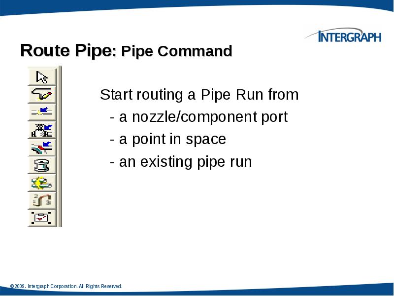
- 14. Route Pipe: Cardinal Points
- 15. Route Pipe: Pipe Run Dialog Box Define the Pipe Run properties
- 16. Route Pipe: Route Pipe Ribbon bar
- 17. Route Pipe: Turn Type Option
- 18. Route Pipe: Graphics Toggle
- 19. Route Pipe: Length Control Tool
- 20. Route Pipe: Route Using Spherical Coordinates Relative Tracking Mode
- 21. Route Pipe: Offset Value Offset Control Tool If the reference object
- 22. Route Pipe: Offset value How the Solver finds the offset:
- 23. Route Pipe: SmartSketch
- 24. Route Pipe: PinPoint PinPoint provides coordinate inputs to the route command.
- 25. Route Pipe: Smart Step Ribbon Bar
- 26. Route Pipe: Working Plane Control Tool
- 27. Pipe Select Command Provides specific filters: Workspace Explorer (set the filter
- 28. Delete a Pipeline Deleting a pipeline deletes all pipe runs, features,
- 29. Delete a Pipe Run Deleting the run deletes all features (and
- 30. Delete Straight Features Example:
- 31. Run To or From End Features or Nozzle When you select
- 32. Routing To or From a Straight Feature Use the Route Pipe
- 33. Insert Component
- 34. Insert Component :Insert Component Ribbon Bar
- 35. Insert Component : Graphical Positioning Reference Position option: The
- 36. Insert Component : Graphical Positioning Flip option: Toggles through the ports
- 37. Insert Component : Mating
- 38. Insert Component : Positioning & Placement
- 39. Routing Sloped Pipe Underground piping collects drains from funnels or catch
- 41. Routing Sloped Pipe Specify Slope on New Run Properties page
- 42. Routing Sloped Pipe: Slope Direction Specify Slope Direction Turn Slope
- 44. Routing Sloped Pipe :Angle Control Tool
- 45. Piping Practice Labs Route Pipes Inserting Components in a Pipe Run
- 46. Integrated Environment While designing or creating a plant in
- 47. Retrieving Data from a P&ID You can retrieve piping,
- 49. Insert Component by its Engineering Tag The engineering tag will be
- 50. Instrument & Piping Specialty Placement We have two types of piping
- 51. Instrument & Piping Specialty Placement Placing piping specialty/instruments
- 52. Instruments
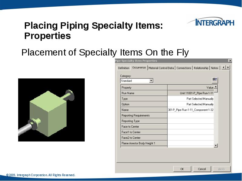
- 54. Placing Piping Specialty Items Specialty items are piping components that are
- 55. Piping Specialty Items Types Stock specialty items: These items represents the
- 57. Insert Tap Use this command when in need to tap a
- 58. Inserting Splits : Insert Split Command Bar
- 59. Inserting Splits : Insert Split Ribbon Bar
- 61. Inserting Splits : Attribute Break Edit Pipe Run properties during modeling
- 62. Piping Practice Labs Routing Pipes from P&ID Placing Piping Instruments
- 63. Piping Manipulation : Edit Straight Features
- 64. Piping Manipulation : Edit End Features
- 65. Piping Manipulation : Edit Run Change Features
- 66. Piping Manipulation : Editing Features
- 67. Piping Manipulation : Editing Features
- 68. Piping Manipulation : Editing Features
- 74. Piping Properties :Edit Properties Command Edit Pipe Run properties. Features inherit
- 75. Piping Properties : Flow Direction Flow Direction Downstream is the direction
- 76. Piping Properties : Edit Properties Dialog Box Insulation
- 77. Piping Properties : Edit Properties Dialog Box Edit Pipe Run properties
- 80. Creating Spools Generation of Spools Generate Spools
- 81. Generation of Spools Generation of Spools Create Penetration Spools
- 82. Naming of Spools Naming of Spools Spooling options always
- 83. Breaks at unions by system Breaks at unions by system Breaks
- 86. Piping Practice Labs Manipulating Piping Objects Creating Spools Sequencing Objects Creating
- 88. Скачать презентацию


Слайды и текст этой презентации
Слайд 1
Описание слайда:
Piping Task
Слайд 2
Описание слайда:
Agenda
Piping Hierarchy
Route Pipes
Inserting Components
Routing a Sloped Pipe
Routing Pipes from the P&ID
Placing Instruments
Placing Piping Specialty Items
Placing Taps
Inserting Splits
Слайд 3
Описание слайда:
Agenda Conti’
Manipulating Views
Creating Spools
Sequencing Objects
Creating Isometric Drawings
Слайд 4
Описание слайда:
- Piping System System and Spec Task
- Piping System System and Spec Task
- Pipeline System
- Pipe Run
- Features
- Parts/Components
- Ports
- Connections
Слайд 5
Описание слайда:
Piping Hierarchy: Pipe System
A piping system is a way of organizing pipelines within the system hierarchy. You can base the piping system on the area where the pipelines are located or the fluid that the pipelines carry.
Слайд 6
Описание слайда:
Piping Hierarchy: Pipeline
A pipeline system is a way of organizing pipe runs within the system hierarchy and controlling the specifications that can be used within that system. If a pipeline system exists in a model, you can route the pipe runs and arrange them as children in the system hierarchy.
Слайд 7
Описание слайда:
Piping Hierarchy: Pipe Run
A pipe run is a connected series of the pipe features that normally have the same nominal piping diameter (NPD) and flow direction. All the pipe runs in a model are governed by the same piping specifications. All the pipe features belong to a pipe run. One or more pipe runs together form a pipeline.
Слайд 8
Описание слайда:
PIPING HIERARCHY: PIPE FEATURES
A pipe feature is a logical collection of parts driven by the pipe specification. While routing a pipe run, you can place features on the pipe; these features define high-level design information. The software automatically selects the specific parts based on the pipe specification of the pipe run. Features are not displayed in the workspace explorer because of their ability to own several parts.
Слайд 9
Описание слайда:
Piping Hierarchy: Pipe Parts
A piping part is a physical component that comprises a feature and is generally selected by the software. Figure 3 shows some examples of pipe parts that represent a section of a piping system. The highlighted portion in the figure shows a section of the workspace explorer containing the hierarchy of the pipe parts.
Слайд 10
Описание слайда:
Piping Hierarchy: Pipe Port
Is the actual connection point for the part.
Слайд 11
Описание слайда:
Piping Hierarchy: Pipe Connections
Provide the connectivity model between ports of different components, nozzles and pipes (welded, bolted, etc...)
Слайд 12
Описание слайда:
Piping Hierarchy: Overview
Слайд 13
Описание слайда:
Слайд 14
Описание слайда:
Route Pipe: Cardinal Points
Слайд 15
Описание слайда:
Route Pipe: Pipe Run Dialog Box
Define the Pipe Run properties
Слайд 16
Описание слайда:
Route Pipe: Route Pipe Ribbon bar
Слайд 17
Описание слайда:
Route Pipe: Turn Type Option
Слайд 18
Описание слайда:
Route Pipe: Graphics Toggle
Слайд 19
Описание слайда:
Route Pipe: Length Control Tool
Слайд 20
Описание слайда:
Route Pipe: Route Using Spherical Coordinates
Relative Tracking Mode
Слайд 21
Описание слайда:
Route Pipe: Offset Value
Offset Control Tool
If the reference object is a planar surface or linear element, the offset distance is measured from the surface or line to the indicated reference plane on the pipe being routed. Five offset reference are available.
An offset SmartSketch point is found on either side of the referenced plane or linear element.
Слайд 22
Описание слайда:
Route Pipe: Offset value
How the Solver finds the offset:
Слайд 23
Описание слайда:
Route Pipe: SmartSketch
Слайд 24
Описание слайда:
Route Pipe: PinPoint
PinPoint provides coordinate inputs to the route command.
x,y,z coordinates are relative to Target Point.
Relative Tracking Mode.
Слайд 25
Описание слайда:
Route Pipe: Smart Step Ribbon Bar
Слайд 26
Описание слайда:
Route Pipe: Working Plane Control Tool
Слайд 27
Описание слайда:
Pipe Select Command
Provides specific filters:
Workspace Explorer (set the filter to all and key in the string in the field to find an object).
Tools > Select by Filter
Слайд 28
Описание слайда:
Delete a Pipeline
Deleting a pipeline deletes all pipe runs, features, and parts associated with that pipeline.
Слайд 29
Описание слайда:
Delete a Pipe Run
Deleting the run deletes all features (and thereby all parts) belonging to the run.
The software attempts to maintain the design integrity of the model by adjusting all previously connected features.
Слайд 30
Описание слайда:
Delete Straight Features
Example:
Слайд 31
Описание слайда:
Run To or From End Features or Nozzle
When you select an end feature during the creation of a pipe run, the Route Pipe command joins the run with the end feature and inherits the properties of the run that the end feature belongs to.
Слайд 32
Описание слайда:
Routing To or From a Straight Feature
Use the Route Pipe command
Branch on Pipe Run
Слайд 33
Описание слайда:
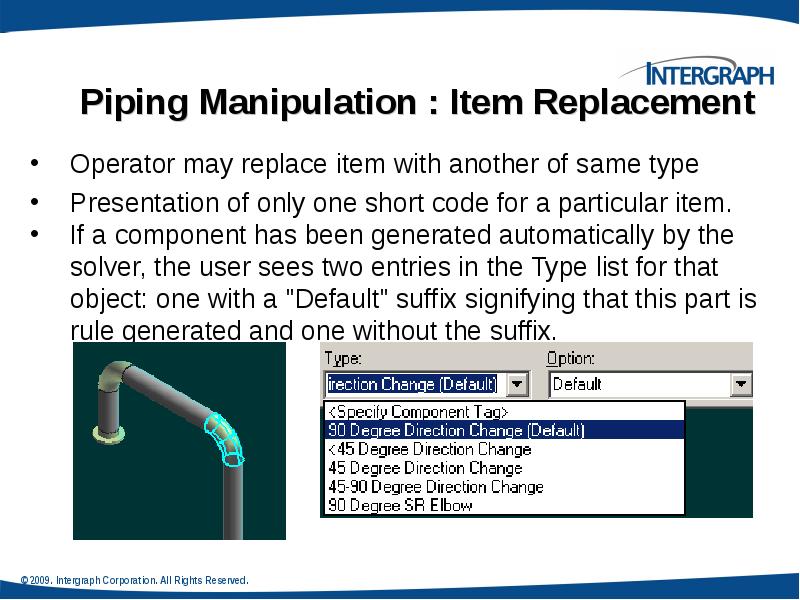
Insert Component
Слайд 34
Описание слайда:
Insert Component :Insert Component Ribbon Bar
Слайд 35
Описание слайда:
Insert Component : Graphical Positioning
Reference Position option:
The system should slide the component along the path so that the select position (example: Origin) is located at the insertion point.
Слайд 36
Описание слайда:
Insert Component : Graphical Positioning
Flip option:
Toggles through the ports available for the component being inserted. As each port is toggled, the component is oriented so that the selected port is aligned along the axis of the leg on which it is being inserted.
Слайд 37
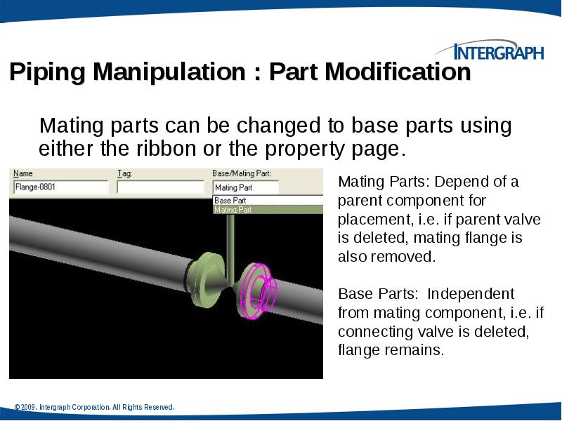
Описание слайда:
Insert Component : Mating
Слайд 38
Описание слайда:
Insert Component : Positioning & Placement
Слайд 39
Описание слайда:
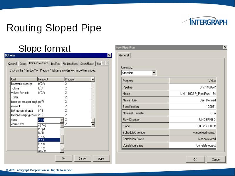
Routing Sloped Pipe
Underground piping collects drains from funnels or catch basins and transports them to a disposal point. Since there is no pressure in this piping system, the pipe must slope for flow.
Слайд 40
Описание слайда:
Слайд 41
Описание слайда:
Routing Sloped Pipe
Specify Slope on New Run Properties page
Слайд 42
Описание слайда:
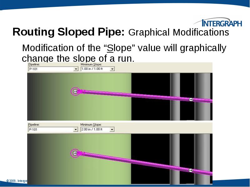
Routing Sloped Pipe: Slope Direction
Specify Slope Direction
Turn Slope Lock On/Off
Слайд 43
Описание слайда:
Слайд 44
Описание слайда:
Routing Sloped Pipe :Angle Control Tool
Слайд 45
Описание слайда:
Piping Practice Labs
Route Pipes
Inserting Components in a Pipe Run
Routing Sloped Pipe
Слайд 46
Описание слайда:
Integrated Environment
While designing or creating a plant in SP3D, you can reuse existing data from other design or authoring tools rather than creating a model from scratch. SmartPlant Foundation (SPF) supports the integration of engineering tools, such as SmartPlant® P&ID, SP3D, SmartPlant Instrumentation, and Aspen Zyqad. This integration addresses the flow of data as it moves from one engineering application to another through its lifecycle.
In an integrated environment, you publish and retrieve data from and to SP3D by using a central repository. During a publish operation, data such as drawings, reports, and 3D models transfers to a central repository. During a retrieve operation, the system retrieves P&IDs, Plant Break Down Structure, Project List, Work Breakdown Structure, Electrical Cable Schedules, and Instrumentation Dimensional Data Sheets from the central repository
Слайд 47
Описание слайда:
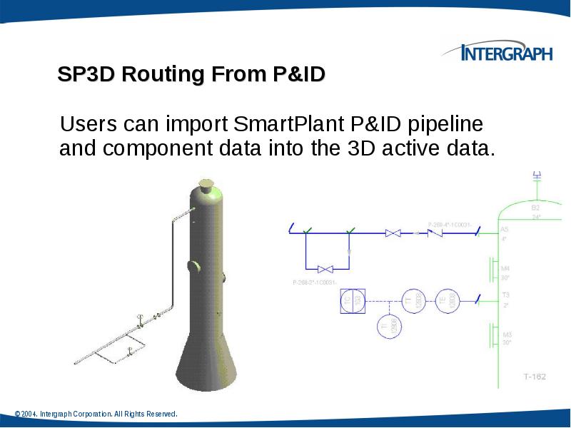
Retrieving Data from a P&ID
You can retrieve piping, instrumentation, and equipment data from P&ID in the integrated environment. You can use P&ID to access items, such as equipment, piping information, and SmartPlant Instrumentation dimension data, to help create the appropriate 3D design objects. For example, after you retrieve data from P&ID, you can use the P&ID File Viewer window in SP3D for guidance in routing pipes, inserting components and instruments, and placing equipment in the 3D model.
Слайд 48
Описание слайда:
Слайд 49
Описание слайда:
Insert Component by its Engineering Tag
The engineering tag will be available on the P&ID, and may be used to select a piping commodity from the Piping Specification.
Слайд 50
Описание слайда:
Instrument & Piping Specialty Placement
We have two types of piping specialty/instrument Parts:
1. Stock item: Stock items represent those piping items that are purchased from a manufacturer’s catalog, where no real engineering is required other than selecting the correct size, material, etc.
2. Custom-engineered item: custom engineered items are built items according to the process.
Слайд 51
Описание слайда:
Instrument & Piping Specialty Placement
Placing piping specialty/instruments
Слайд 52
Описание слайда:
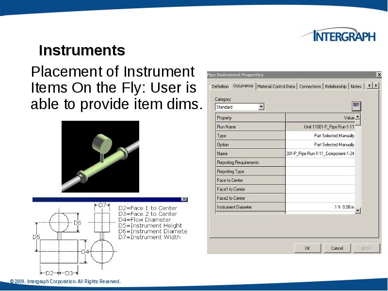
Instruments
Слайд 53
Описание слайда:
Слайд 54
Описание слайда:
Placing Piping Specialty Items
Specialty items are piping components that are not defined as a part of piping specification. Just like instruments, you can place specialty items in a pipeline to perform a specific task.
Слайд 55
Описание слайда:
Piping Specialty Items Types
Stock specialty items: These items represents the piping items purchased from a manufacturer’s catalog, where no real engineering is required other than selecting the correct size and material.
Custom specialty items: These items are typically driven by parameters. Therefore, you can change their size and shape after placing them in the model.
Слайд 56
Описание слайда:
Слайд 57
Описание слайда:
Insert Tap
Use this command when in need to tap a drain, vent, or instrument connection. Used to place taps on all piping components; elbows, tees, caps, valves, pipes, and so forth; except for mating parts.
Слайд 58
Описание слайда:
Inserting Splits : Insert Split Command Bar
Слайд 59
Описание слайда:
Inserting Splits : Insert Split Ribbon Bar
Слайд 60
Описание слайда:
Слайд 61
Описание слайда:
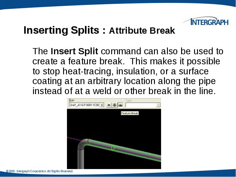
Inserting Splits : Attribute Break
Edit Pipe Run properties during modeling to create an attribute break.
When the run properties are changed, the corresponding feature properties are automatically changed as well.
When NPD is changed, reducers are selected from the spec to satisfy the NS change.
Слайд 62
Описание слайда:
Piping Practice Labs
Routing Pipes from P&ID
Placing Piping Instruments
Placing Piping Specialty Items
Placing Taps
Placing Splits
Слайд 63
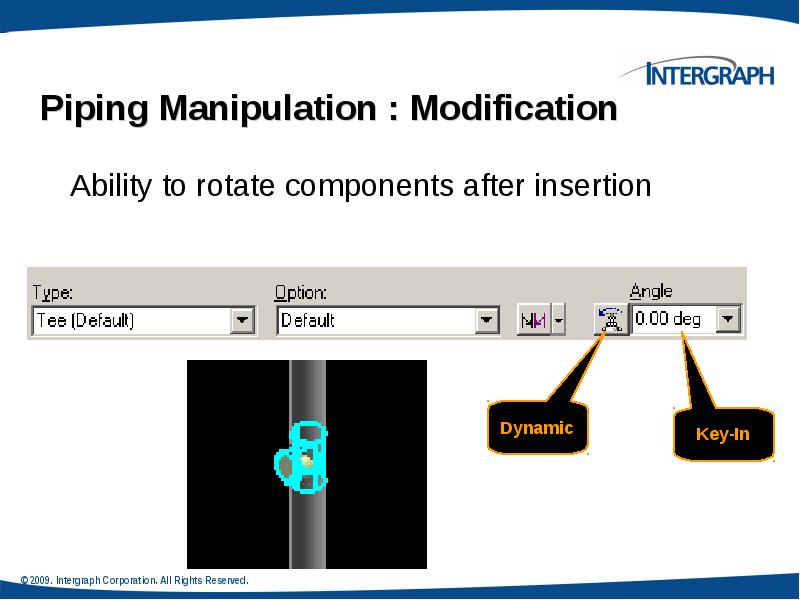
Описание слайда:
Piping Manipulation : Edit Straight Features
Слайд 64
Описание слайда:
Piping Manipulation : Edit End Features
Слайд 65
Описание слайда:
Piping Manipulation : Edit Run Change Features
Слайд 66
Описание слайда:
Piping Manipulation : Editing Features
Слайд 67
Описание слайда:
Piping Manipulation : Editing Features
Слайд 68
Описание слайда:
Piping Manipulation : Editing Features
Слайд 69
Описание слайда:
Слайд 70
Описание слайда:
Слайд 71
Описание слайда:
Слайд 72
Описание слайда:
Слайд 73
Описание слайда:
Слайд 74
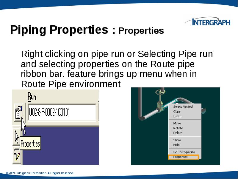
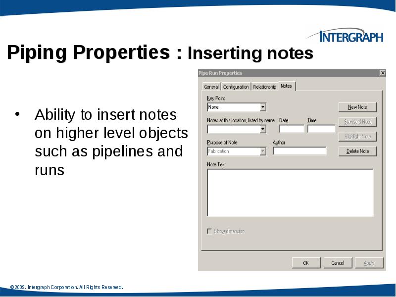
Описание слайда:
Piping Properties :Edit Properties Command
Edit Pipe Run properties.
Features inherit the
common properties of
the run by default.
Слайд 75
Описание слайда:
Piping Properties : Flow Direction
Flow Direction
Downstream is the direction from the start to the end of the run
Слайд 76
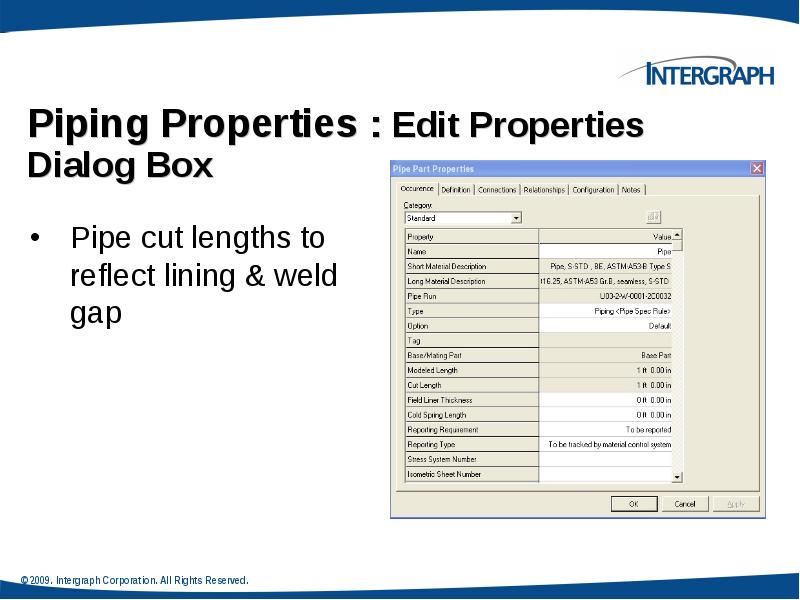
Описание слайда:
Piping Properties : Edit Properties Dialog Box
Insulation
Слайд 77
Описание слайда:
Piping Properties : Edit Properties Dialog Box
Edit Pipe Run properties
Relation Tab displays all the relationships defined for the selected pipe run.
Слайд 78
Описание слайда:
Слайд 79
Описание слайда:
Слайд 80
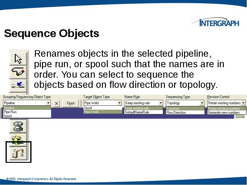
Описание слайда:
Creating Spools
Generation of Spools
Generate Spools
Слайд 81
Описание слайда:
Generation of Spools
Generation of Spools
Create Penetration Spools
Слайд 82
Описание слайда:
Naming of Spools
Naming of Spools
Spooling options always default to those defined in the Catalog with interactive setting changes persisting for the current session only.
Слайд 83
Описание слайда:
Breaks at unions by system
Breaks at unions by system
Breaks at user defined control points
Слайд 84
Описание слайда:
Слайд 85
Описание слайда:
Слайд 86
Описание слайда:
Piping Practice Labs
Manipulating Piping Objects
Creating Spools
Sequencing Objects
Creating Isometric Drawings
Слайд 87
Описание слайда:
Скачать презентацию на тему Piping Task можно ниже: